ROS
|
Remote Observation Station

|
Motorola's
Flash Innovation 2003
Design Contest
|
This page summarizes the prototype that was entered in Motorola's Flash Innovation 2003 Design Contest.
Its design was chosen Grand Prize winner.
For a detailed description of this project you can download the contest write-up here, or from Circuit Cellar Magazine, who administered the contest. A shorter more concise article about this project also appears in the January 2004 issue of Circuit Cellar.
Project Abstact:
Have you ever wondered what the birds, deer, or bears were doing in your backyard when you weren't around?
With the Remote Observation Station, you can watch wildlife on your TV in the comfort
of your living room. The station includes a camera and transmitter that sends a picture to a TV, which can be up to a mile
or two away. The station gets its power from a PV solar panel and a rechargeable battery, which rely on the system's
control board for direction. The control board also produces battery state information, which it overlays on the picture sent to your TV.
 So, while you're watching the wildlife, you can also monitor the status of your battery.
The unit integrates six electronic devices, including a CCD video camera, PV solar
panel, rechargeable battery, temperature sensor, RF video transmitter, and the system
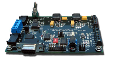
control board (PVCC). The control board is based on the Motorola 68HC908QY4 microcontroller.
The board sits at the center of the system, providing a PV charge controller,
two high-efficiency voltage regulators, a video sync separator, and an RS-232 serial interface
for system configuration.
The PVCC control board provides a simple on/off battery charger using the PV solar
panel as a power source. The primary job of the charge controller is to prevent the battery
from being overcharged. The control board also adds battery state information in the
form of a text overlay (on-screen display, or OSD) to the video signal generated by the
CCD camera before it reaches the video transmitter. Additionally, a PC can be connected
to the control board via the DB9 connector.
The system has three operating modes: Configuration mode allows you to control
user settings with your PC; Charge Control mode with OSD sends the battery's voltage
and temperature to the video signal; and Charge Control mode without OSD is used when you
don't need the diagnostic display. The PVCC configuration utility communicates with the
PVCC board while in Configuration mode. With this utility, you can set a variety of options,
including the full-charge set point (the off set point) and the PV reconnect set point (the on
set point). You can also choose to enable the transmission of an Amateur Radio call sign if a
ham frequency is being used.
So, while you're watching the wildlife, you can also monitor the status of your battery.
The unit integrates six electronic devices, including a CCD video camera, PV solar
panel, rechargeable battery, temperature sensor, RF video transmitter, and the system
control board (PVCC). The control board is based on the Motorola 68HC908QY4 microcontroller.
The board sits at the center of the system, providing a PV charge controller,
two high-efficiency voltage regulators, a video sync separator, and an RS-232 serial interface
for system configuration.
The PVCC control board provides a simple on/off battery charger using the PV solar
panel as a power source. The primary job of the charge controller is to prevent the battery
from being overcharged. The control board also adds battery state information in the
form of a text overlay (on-screen display, or OSD) to the video signal generated by the
CCD camera before it reaches the video transmitter. Additionally, a PC can be connected
to the control board via the DB9 connector.
The system has three operating modes: Configuration mode allows you to control
user settings with your PC; Charge Control mode with OSD sends the battery's voltage
and temperature to the video signal; and Charge Control mode without OSD is used when you
don't need the diagnostic display. The PVCC configuration utility communicates with the
PVCC board while in Configuration mode. With this utility, you can set a variety of options,
including the full-charge set point (the off set point) and the PV reconnect set point (the on
set point). You can also choose to enable the transmission of an Amateur Radio call sign if a
ham frequency is being used.
|
|